
GPIO Programming: Using the sysfs Interface
In this blog post we'll look at basic GPIO control using the sysfs interface provided by the Linux kernel. We won't need to do any programming as we can do this from shell commands. I'll show some examples that will work on the Raspberry Pi platform.
Background
As we'll see in future installments of this blog series, there are different ways to access GPIO hardware from programs, but sysfs is a simple one that is supported by the Linux kernel and makes the devices visible in the file system so we can experiment from the command line without needing to write any code. For simple applications you can use it this way, either interactively or by putting the commands in shell scripts.
Sysfs is a pseudo filesystem provided by the Linux kernel that makes information about various kernel subsystems, hardware devices, and device drivers available in user space through virtual files. GPIO devices appear as part of sysfs.
Before we continue, I should mention that this interface is being deprecated in favor of a new GPIO character device API. The new API addresses a number of issues with the sysfs interface. However, it can't be easily be used from the file system like sysfs, so the examples here will use sysfs, which is still going to be supported for some time.
If you want to follow along and try these commands on a Raspberry Pi, you should check that you did the setup mentioned in the last blog post, specifically you need to be part of the "gpio" group so you can run these commands without the need to become the root user.
Basic Steps
If your system has a suitable sysfs driver loaded, you will see the GPIO hardware exposed in the file system under /sys/class/gpio. On a Raspberry Pi it might look something like this:
$ ls /sys/class/gpio/
export*  gpiochip0@  gpiochip100@  gpiochip504@  unexport*
We'll look at how to use this interface next. Note that the device names starting with "gpiochip" are the GPIO controllers and we won't directly use them.
The basic steps to use a GPIO pin from the sysfs interface are the following:
- Export the pin.
- Set the pin direction (input or output).
- If an output pin, set the level to low or high.
- If an input pin, read the pin's level (low or high).
- When done, unexport the pin.
To export a pin, we write the pin name/number to the pseudo file /sys/class/gpio/export. This indicates that we want to use a specific GPIO pin and makes it visible in the sysfs file system hierarchy. Later when we are done, we can unexport the pin. Needing to explicitly export a pin can help prevent errors where one might inadvertently attempt to access the wrong pin.
As an example, we can export GPIO pin 24 (which corresponds to physical pin number 18 on the GPIO connector of the Raspberry Pi) with this shell command:
$ echo 24 >/sys/class/gpio/export
We will now see a gpio24 device appear under /sys/class gpio that was not there before:
$ ls /sys/class/gpio
export*  gpio24@  gpiochip0@  gpiochip100@  gpiochip504@  unexport*
This is a symbolic link to a directory which has a number of files in it:
$ ls /sys/class/gpio/gpio24/
active_low*  device@  direction*  edge*  power/  subsystem@  uevent*  value*
Step 2 is to set the pin to be either an input or an output. This is done by writing either "in", or "out" to the direction file we saw above. For example, to set gpio24 as an input we would do:
$ echo in >/sys/class/gpio/gpio24/direction
Or to set it as an output:
$ echo out >/sys/class/gpio/gpio24/direction
The file can be read back if you want to check the current status:
$ cat /sys/class/gpio/gpio24/direction
out
While this may not be true for all hardware, a GPIO pin will generally default to being an input as this is always safe to do at the hardware level.
If we are configuring an output pin, we can now set it's level. You write the value 0 or 1 (corresponding to low or high) to the value file for the pin. Continuing our example this could be done with:
$ echo 0 >/sys/class/gpio/gpio24/value
to set it low, or
$ echo 1 >/sys/class/gpio/gpio24/value
to set it high.
If we had configured the pin as an input and tried to do this, we would get an error because it is not valid to set the value of an input pin:
bash: echo: write error: Operation not permitted
If it had been configured as an input pin, we can read its value using the same file:
$ cat /sys/class/gpio/gpio24/value
0
In this case 0 or low.
You may be wondering if it is valid to read the value of an output pin, and the answer is yes. The value you read back depends on the actual hardware. On the Raspberry Pi you should see the same value that was output, but on some hardware it may reflect the actual signal level, which may be different if external hardware is driving it high or low.
The final step, if you are finished using the GPIO pin, is to unexport it. To do this, just write the pin name to the unexport file, i.e.
$ echo 24 >/sys/class/gpio/unexport
After doing this, the entry for gpio24 will no longer appear in sysfs:
$ ls /sys/class/gpio
export*  gpiochip0@  gpiochip100@  gpiochip504@  unexport*
Example Hardware/Circuit
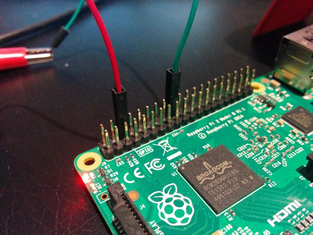
If you want to actually try this on the Raspberry Pi hardware, you could connect a digital multimeter across pin 18 (GPIO24) and pin 6 (GROUND) of the Raspberry Pi GPIO header. Set your DMM to the DC volts function. The picture below shows the hardware setup:
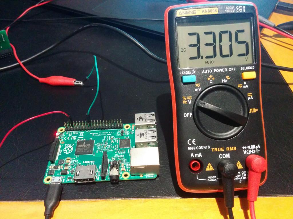
Run these commands and you should see approximately 3.3 volts (a logic high level) on the multimeter:
$ echo 24 >/sys/class/gpio/export
$ echo out >/sys/class/gpio/gpio24/direction
$ echo 1 >/sys/class/gpio/gpio24/value
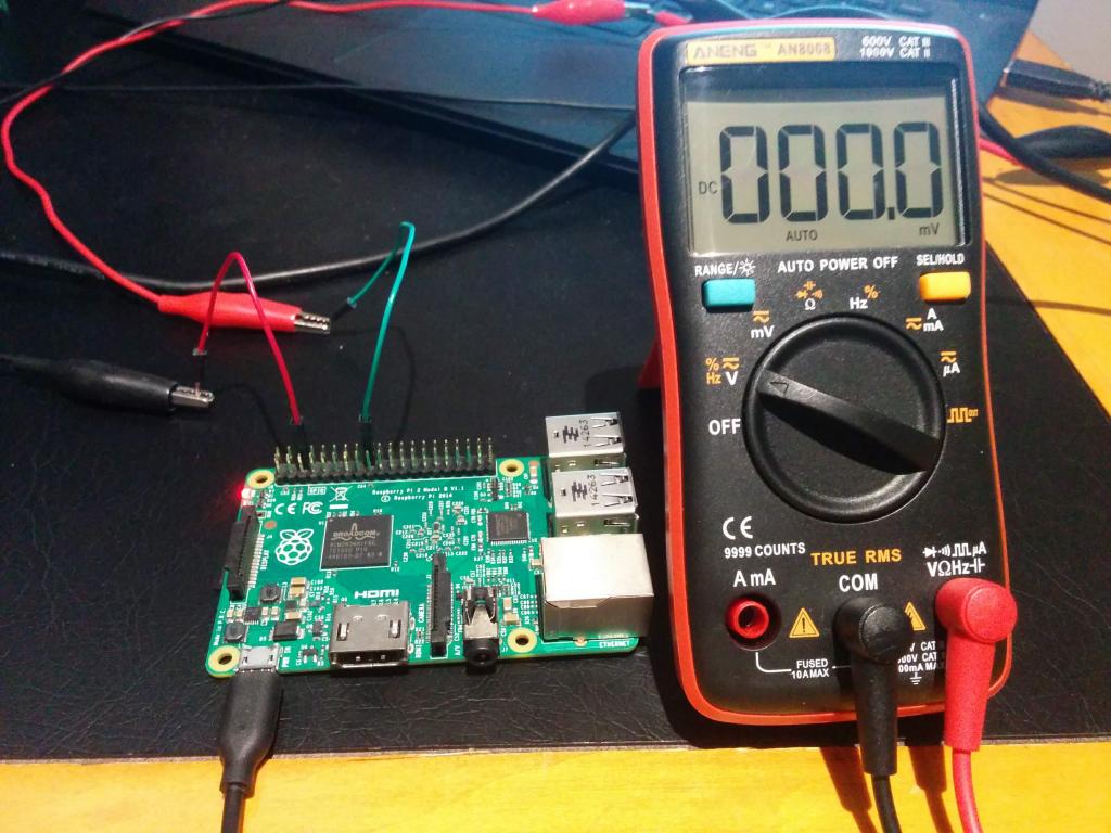
Now set the value to low and it should read close to zero:
$ echo 0 >/sys/class/gpio/gpio24/value
You can also try reading the pin as an input. If you carefully connect a jumper wire between pin 18 (GPIO24) and pin 6 (GND) it should read a low when you run these commands (don't connect the jumper wire until you've run these commands, because we want to make sure that it is not connected to ground if it was previously set to be an output):
$ echo in >/sys/class/gpio/gpio24/direction
$ cat /sys/class/gpio/gpio24/value
0
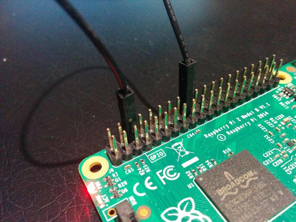
Now, if you connect pin 18 to pin 1 (3.3V) it should report the input as high:
$ cat /sys/class/gpio/gpio24/value
1
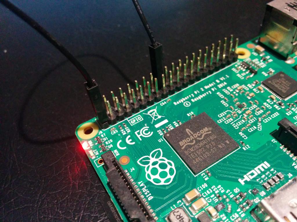
Be very careful you don't connect the wrong pins or you can damage your Raspberry Pi!
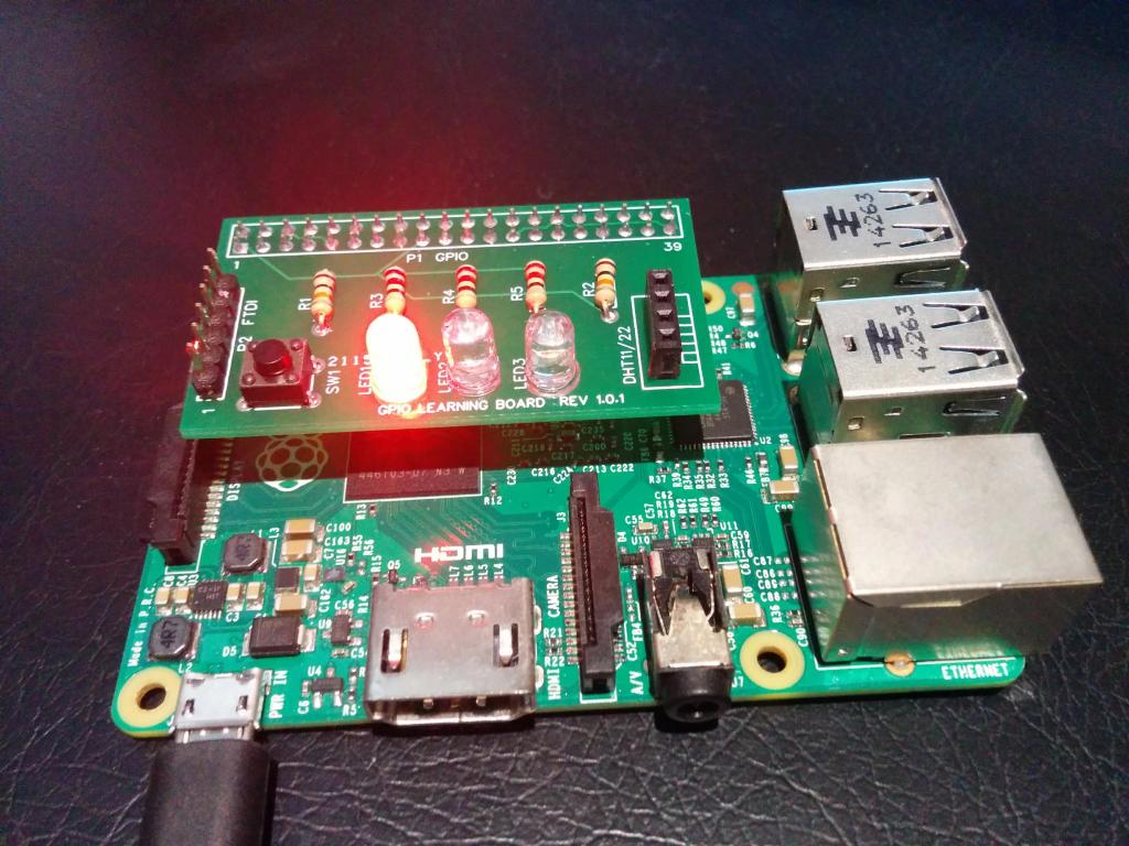
If you have hardware knowledge and some parts handy, you could breadboard up a little circuit with an LED and current limiting resistor instead of the DMM and turn the LED on and off. Similarly, you can hook up a switch and a pullup resistor to test an input pin. There are many good tutorials around showing how to do this on the Raspberry Pi.
In our training classes we use this little board that has three LEDs, as well as a switch that can be read:
Doing More
There are more functions that can be done with GPIO pins that aren't easily done from the sysfs interface. Most Raspberry Pi GPIO pins support enabling internal pullup and pulldown resistors and you can have an interrupt generated when an input pin changes level. We'll cover some of these in future when we look at other programming interfaces.
The gpio Utility
On the Raspberry Pi platform there is a handy command line utility called "gpio" which can control the pins more conveniently than using the sysfs interface. It can export pins, set direction, set and read levels, as well as more advanced functions like PWM. It should be installed by default under Raspbian Linux. If not, just run "sudo apt install wiringpi" to install it.
Here is the command usage:
$ gpio -h
gpio: Usage: gpio -v
       gpio -h
       gpio [-g|-1] ...
       gpio [-d] ...
       [-x extension:params] [[ -x ...]] ...
       gpio [-p] <read/write/wb> ...
       gpio <mode/read/write/aread/awritewb/pwm/pwmTone/clock> ...
       gpio <toggle/blink> <pin>
       gpio readall
       gpio unexportall/exports
       gpio export/edge/unexport ...
       gpio wfi <pin> <mode>
       gpio drive <group> <value>
       gpio pwm-bal/pwm-ms
       gpio pwmr <range>
       gpio pwmc <divider>
       gpio load spi/i2c
       gpio unload spi/i2c
       gpio i2cd/i2cdetect
       gpio rbx/rbd
       gpio wb <value>
       gpio usbp high/low
       gpio gbr <channel>
       gpio gbw <channel> <value>
Running "man gpio" will show the documentation for the command. One useful option will read and display all the GPIO pins, with a representation of the pin numbers and names:
$ gpio readall
 +-----+-----+---------+------+---+---Pi 3B--+---+------+---------+-----+-----+
 | BCM | wPi |   Name  | Mode | V | Physical | V | Mode | Name    | wPi | BCM |
 +-----+-----+---------+------+---+----++----+---+------+---------+-----+-----+
 |     |     |    3.3v |      |   |  1 || 2  |   |      | 5v      |     |     |
 |   2 |   8 |   SDA.1 |   IN | 1 |  3 || 4  |   |      | 5v      |     |     |
 |   3 |   9 |   SCL.1 |   IN | 1 |  5 || 6  |   |      | 0v      |     |     |
 |   4 |   7 | GPIO. 7 |   IN | 1 |  7 || 8  | 1 | ALT5 | TxD     | 15  | 14  |
 |     |     |      0v |      |   |  9 || 10 | 1 | ALT5 | RxD     | 16  | 15  |
 |  17 |   0 | GPIO. 0 |   IN | 0 | 11 || 12 | 0 | IN   | GPIO. 1 | 1   | 18  |
 |  27 |   2 | GPIO. 2 |   IN | 0 | 13 || 14 |   |      | 0v      |     |     |
 |  22 |   3 | GPIO. 3 |   IN | 0 | 15 || 16 | 0 | IN   | GPIO. 4 | 4   | 23  |
 |     |     |    3.3v |      |   | 17 || 18 | 0 | IN   | GPIO. 5 | 5   | 24  |
 |  10 |  12 |    MOSI |   IN | 0 | 19 || 20 |   |      | 0v      |     |     |
 |   9 |  13 |    MISO |   IN | 0 | 21 || 22 | 0 | IN   | GPIO. 6 | 6   | 25  |
 |  11 |  14 |    SCLK |   IN | 0 | 23 || 24 | 1 | IN   | CE0     | 10  | 8   |
 |     |     |      0v |      |   | 25 || 26 | 1 | IN   | CE1     | 11  | 7   |
 |   0 |  30 |   SDA.0 |   IN | 1 | 27 || 28 | 1 | IN   | SCL.0   | 31  | 1   |
 |   5 |  21 | GPIO.21 |   IN | 1 | 29 || 30 |   |      | 0v      |     |     |
 |   6 |  22 | GPIO.22 |   IN | 1 | 31 || 32 | 0 | IN   | GPIO.26 | 26  | 12  |
 |  13 |  23 | GPIO.23 |   IN | 0 | 33 || 34 |   |      | 0v      |     |     |
 |  19 |  24 | GPIO.24 |   IN | 0 | 35 || 36 | 0 | IN   | GPIO.27 | 27  | 16  |
 |  26 |  25 | GPIO.25 |   IN | 1 | 37 || 38 | 0 | IN   | GPIO.28 | 28  | 20  |
 |     |     |      0v |      |   | 39 || 40 | 0 | IN   | GPIO.29 | 29  | 21  |
 +-----+-----+---------+------+---+----++----+---+------+---------+-----+-----+
 | BCM | wPi |   Name  | Mode | V | Physical | V | Mode | Name    | wPi | BCM |
 +-----+-----+---------+------+---+---Pi 3B--+---+------+---------+-----+-----+
From our earlier example, we could set gpio24 high and low with these commands:
$ gpio export 24 out
$ gpio -g write 24 1
$ gpio -g write 24 0
Or even toggle (change) the value or make it blink briefly like this:
$ gpio -g toggle 24
$ gpio -g blink 24
And finally, unexport it:
$ gpio unexport 24
Note the use of the -g option -- this tells the command to use the BCM pin numbers rather than the default, which is to use numbers used by the WiringPi library (which we'll look at in a future blog post). A quirk of the command is that when using the export and unexport commands, it always uses the BCM pin numbers, so the -g option is not needed in this case.
Conclusions
The sysfs interface is a good way to start understanding GPIO programming at a low level. Next up in this blog series we'll look at some ways to program GPIO using the Python programming language. If you missed any of the installments, you can find them here.