Explore Hardware Capabilities of Raspberry Pi's GPIO Interface
In part 2 of our series on GPIO programming, we look at the hardware capabilities of the Raspberry Pi's GPIO interface. As you probably know, the Raspberry Pi is a family of low cost single-board computers developed primarily for education by the non-profit Raspberry Pi Foundation. To date over 25 million units of this $35 computer have been sold.
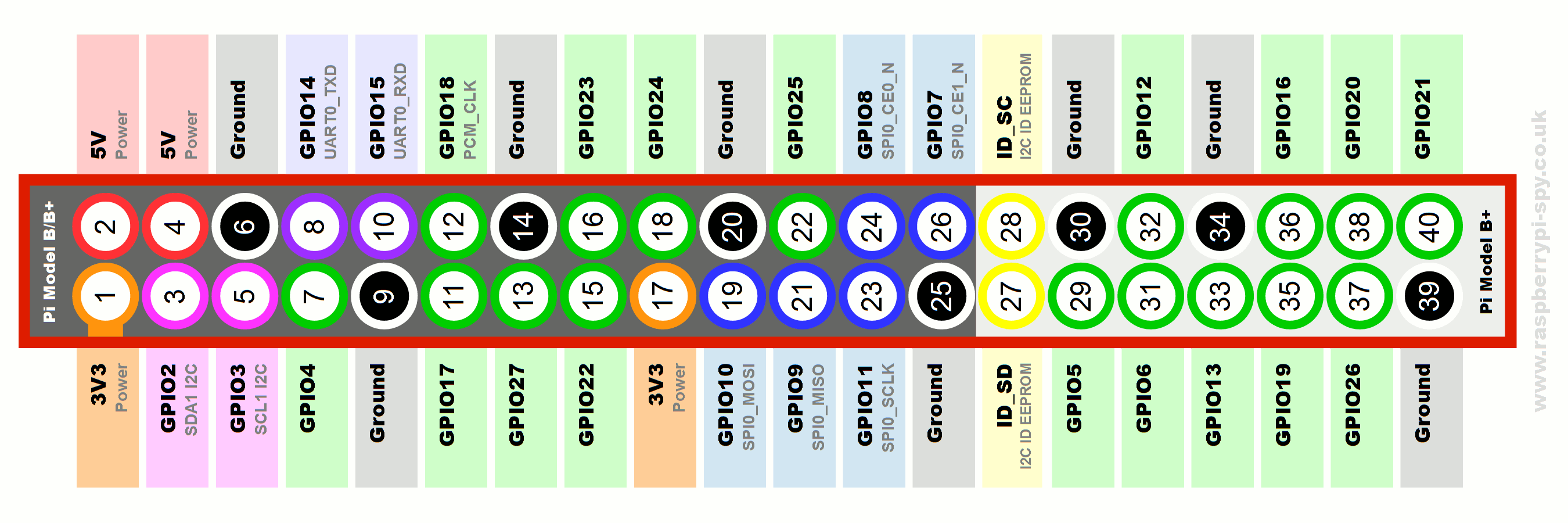
The current models of Raspberry Pi and Raspberry Pi Zero have a 40-pin header connector that provides access to the GPIO pins and some other signals. The header provides access to 26 GPIO pins as well as 5V, 3.3V, ground, and some specialized pins for an ID EEPROM function.

[Source: https://www.raspberrypi-spy.co.uk/2012/06/simple-guide-to-the-rpi-gpio-…]
The 26 GPIO pins can be individually configured as inputs or outputs, and use 3.3V logic levels where a HIGH logic level is represented as nominally 3.3 volts and a LOW by zero volts. They cannot tolerate higher voltages (like 5 volts) without being damaged.
Unconnected inputs typically have an undefined logic level. Pullup or pulldown resistors can be used to force unconnected pins to a high or low level, respectively. This is often done in hardware using external resistors, but can also be done in software. Pins GPIO2 and GPIO3 have fixed pullup resistors on the board, while the other GPIO pins can be configured in software whether to provide a pullup or pulldown resistor (or none).
Functions beyond basic digital I/O are also supported. Some features are available with all pins, and some are only supported by specific pins:
- PWM (pulse-width modulation), is supported in hardware on pins GPIO12, GPIO13, GPIO18, in GPIO19. PWM can also be done in software on any pin.
- Two SPI (Serial Peripheral Interface) ports are provided by GPIO10, GPIO9, GPIO11, GPIO8, GPIO7 and GPIO20, GPIO19, GPIO21, GPIO18, GPIO17, GPIO16.
- An I2C interface is supported by pins GPIO2 and GPIO3.
- On pins GPIO14 and GPIO15 is a serial interface which can be used as a serial console.
We'll cover these interfaces in future blog posts.
As we'll see when we get into programming, it is important to distinguish between the GPIO pin numbers (e.g. GPIO14) and the physical pin numbers of the connectors, which are different (GPIO14 is on pin 8, for example).
If you have a Raspberry Pi and want to use it for GPIO programming, there is some setup you can do now to get things ready. To access the GPIO devices you either need to be user "root" or a user that is a member of the "gpio" group. We can avoid having to become root or run "sudo" every time we want to access GPIO by adding our user account to the gpio group. If you use the default "pi" account you can do this from a shell using this command (shown in bold):
$ sudo adduser pi gpio
Adding user `pi' to group `gpio' ...
Adding user pi to group gpio Done.
If you use a different username, use that name in place of "pi" above. You then need to log out and back in again in order for the new group membership to take effect. You can confirm you are a member of the group by checking that the output of the "groups" command contains "gpio":
$ groups
pi adm dialout cdrom sudo audio video plugdev games users input netdev gpio i2c spi
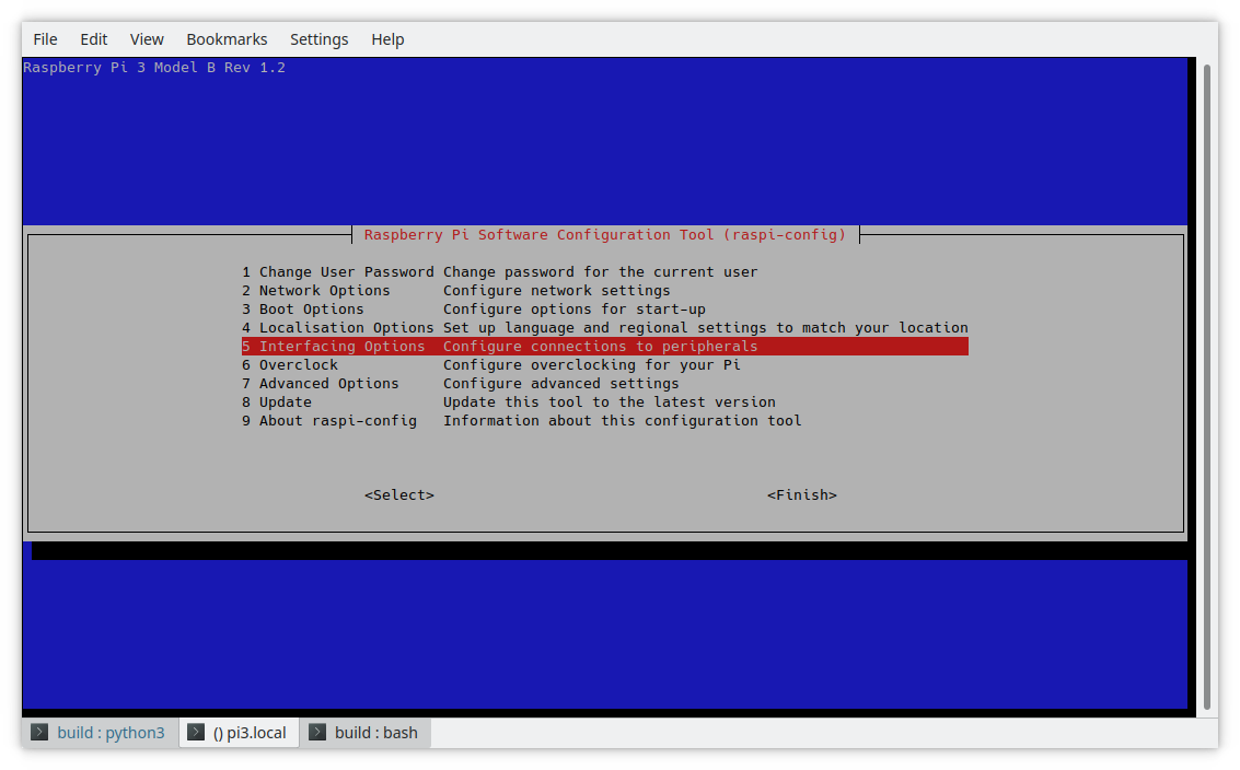
If you plan to experiment with some of the more advanced features of GPIO programming, you can enable them now as well. Run the Raspberry Pi configuration program as root by typing:
$ sudo raspi-config
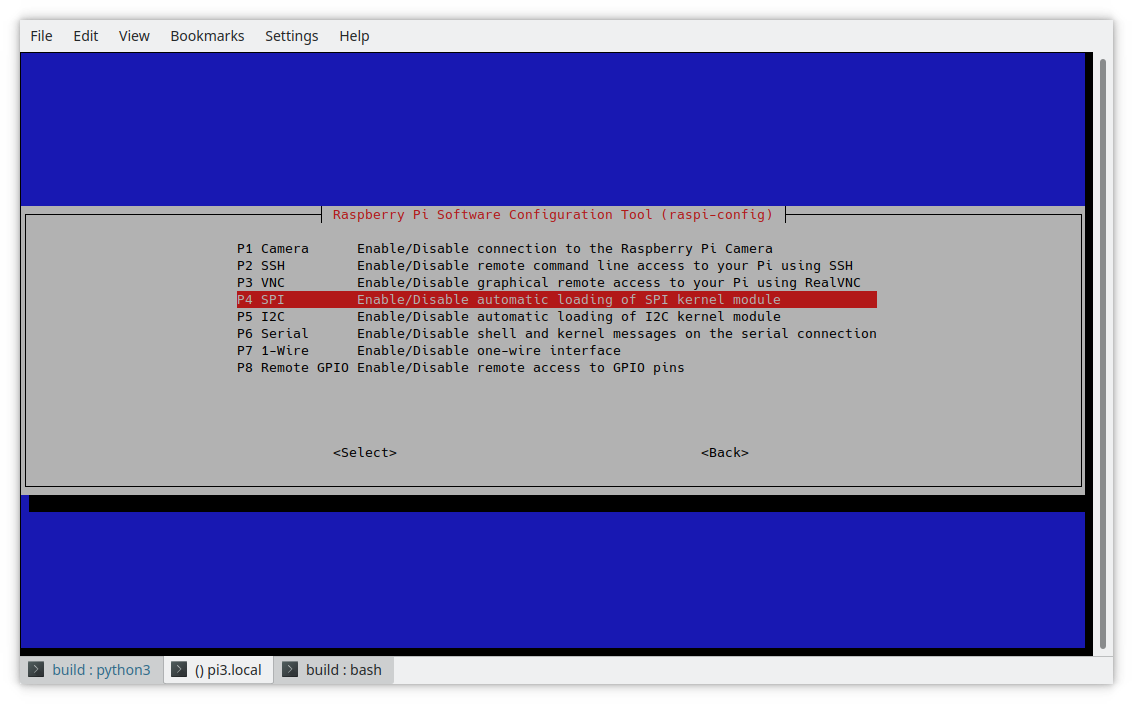
You can then pick "Interfacing Options":

The settings relevant to GPIO are SPI, I2C, Serial, and 1-Wire. You can review and enable them if you think these are interfaces that you plan to use in the future. For basic GPIO programming they can be left disabled.

In part 3, we'll finally get to some hands-on GPIO programming using the sysfs interface. Missed Part 1? Read it here.