An Introduction to GPIO Programming
Editor's note: This 2019 blog series, among ICS' most popular, has been updated (December 2022) to ensure the content is still accurate, relevant and useful.
This blog launches Integrated Computer Solutions' (ICS) new series on GPIO programming. GPIO, or General-Purpose Input/Output, is a feature of most modern embedded computer hardware and a key component of many embedded systems. In this series, I'll cover this important aspect of embedded programming, with a mix of theory and practical programming examples. In this first installment I'll present an overview of GPIO programming, what it can be used for and some basic concepts you need to know in order to use it.
In upcoming posts I explain how to program GPIO, starting with the file system or sysfs interface, as well as from Python (using various modules) and from C or C++. I'll cover the capabilities of some low-cost commercial embedded boards, including the Raspberry Pi series and boards from Toradex. In addition to basic digital input and output functions, I'll address other protocols, such as SPI, I2C, 1-Wire and serial interfaces.
As a bonus, I'll tie some of this low-level programming back to Qt and show an example or two that make use of Qt features. While the specific code examples will be written for the Raspberry Pi or Toradex platforms, the concepts will be applicable to other hardware as long as it is running some form of Linux like Raspbian, Yocto or boot2qt.
What is GPIO?
A GPIO is a signal pin on an integrated circuit or board that can be used to perform digital input or output functions. By design it has no predefined purpose and can be used by the hardware or software developer to perform the functions they choose. Typical applications include controlling LEDs, reading switches and controlling various types of sensors.
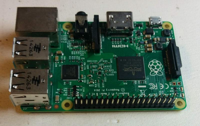
Most models of Raspberry Pi, for example, have a 40-pin GPIO connector that provides access to about 25 GPIO lines.

GPIO may be implemented by dedicated integrated circuits, or more often are directly supported by system on a chip (SoC) or system on a module (SoM) devices.
The most common functions of GPIO pins include:
- Being configurable in software to be input or output
- Being enabled or disabled
- Setting the value of a digital output
- Reading the value of a digital output
- Generating an interrupt when the input changes value
GPIO pins are digital, meaning they only support high/low or on/off levels. They generally don't support analog input or output with many discrete voltage levels. Some GPIO pins may directly support standardized communication protocols like serial communication, SPI, I2C, PCM, and PWM. (I'll cover these in future posts).
Hardware Concepts

If you want to experiment with GPIO programming, you'll need some hardware and tools. In addition to a board like a Raspberry Pi, some useful parts and tools to have include:
- GPIO breakout cable or prototyping board
- Solderless breadboard and jumper wires
- Variety of LEDs, resistors, and switches
- Low-cost digital multimeter
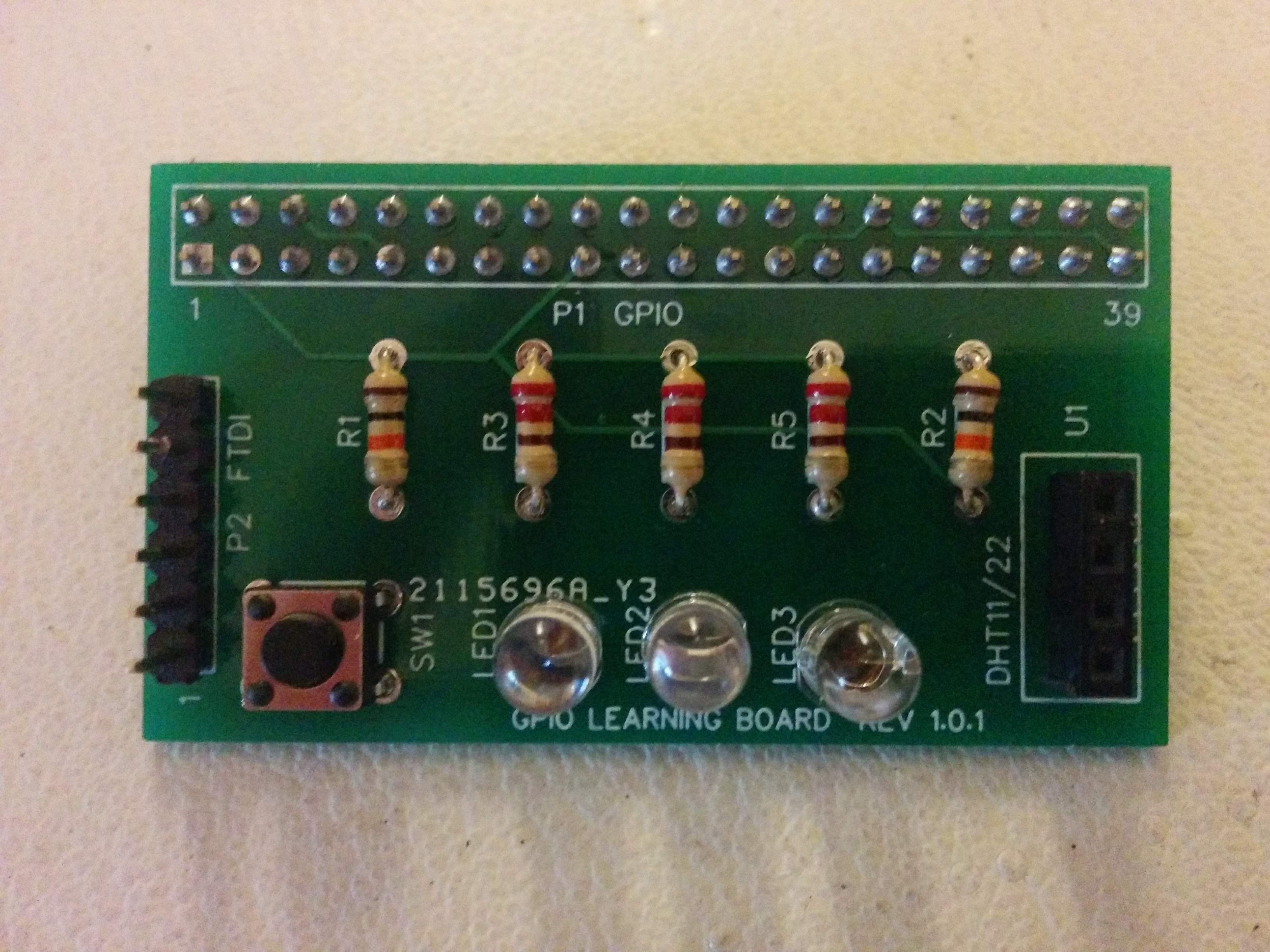
These are available from many vendors such as AdaFruit. There are also various commercially available boards that you can control if you don't want to assemble your own hardware. At ICS, we designed a small GPIO Learning Board (shown below) that we use for our embedded programming classes. I'll describe that in more detail in later posts.

A Word on Safety
If you are new to hardware, a few words on basic safety are in order. Since the voltages on a Raspberry Pi and similar boards are low (5 volts or less), the risk of electric shock is minimal as long as you avoid any circuity that operates on power line voltages.
You should use caution and wear eye protection if you do any soldering or clip wire leads.
The most likely accident is to inadvertently damage your Raspberry Pi or other device. Connecting a GPIO or other pin to the wrong voltage can easily damage the board and render it unusable. Static electricity, especially during the dry winter months, can also generate high voltages that can damage hardware if you develop a static charge and then touch the board. A grounded anti-static mat and/or wrist strap are recommended for your work area.
Also be aware that many devices, including the Raspberry Pi, use 3.3 volt logic levels and can be damaged if connected to 5 volts, which is used by many other devices like Arduino and is present on the GPIO connector.
One Caveat
As someone who often uses the Qt framework for developing applications with graphical user interfaces, I'd like to mention one final caveat. Generally speaking, embedded applications will not do any significant amount of GPIO programming on the same CPU as the one that runs the GUI. Instead, you'll typically want to use another processor or microcontroller, particularly if there are any real-time requirements for controlling the hardware.
Some exceptions to this rule where you might want to do GPIO programming on the same CPU as the GUI can include:
- Low-speed or rarely used functions, such as power on/off switch sensing.
- A design where you're using a real-time operating system (RTOS) and can run code from a process or thread with guaranteed response and latency times.
- Developing an initial prototype or proof of concept with an off-the-shelf board like the Raspberry Pi that is not meant for production use.
- Educational or self-learning applications where performance is not a factor.
Look for more on GPIO programming as this series unfolds. I hope you follow along, try out and modify some of the program examples.